
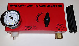
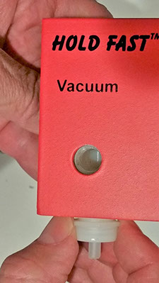
Hold Fast
V812 Vacuum Repair
Check first to see if you have a problem with the V812:
Air escaping from the case is normal if you are generating vacuum. The compressed air that is escaping from the venturi generates the vacuum.
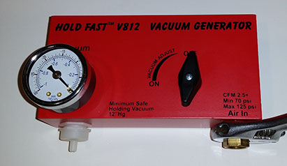
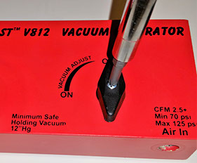
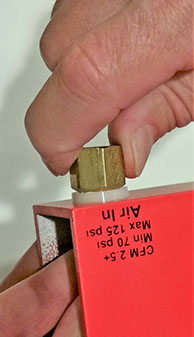
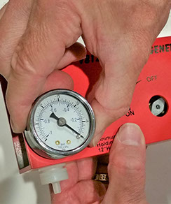
Check to ensure that the air pressure is set to 85 PSI or more. Put finger over white fitting and turn on system.
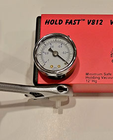
Check vacuum gauge. Maximum achievable vacuum depends on altitude and barometric pressure.
(low pressure = less vacuum)
Normal at sea level is 20"-25"+ hg.
Problems that can occur:
The V812 Vacuum Generator performance can degrade or completely stop if clogged by debris from a dirty compressor, excessive water in the compressor, or excessive dust.
If there is excessive water in the compressor, drain per your compressor manual. Turn vacuum generator back on to dry out Venturi. If water continues to be a problem, a water separator is recommended.
If this is not the problem, it is most likely that some debris is clogging the Venturi.
The following shows you how to completely disassemble, clean, and reassemble the V812.

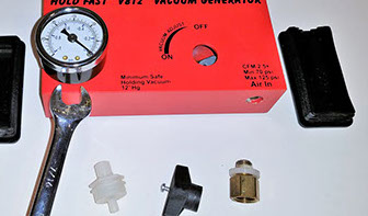
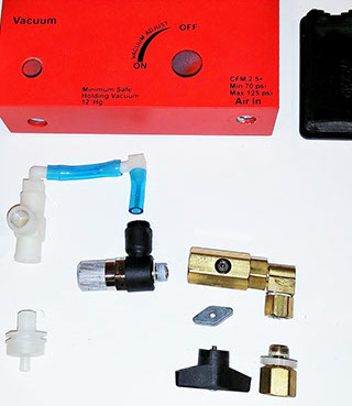
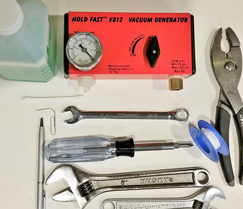
Tools required to repair V812 Vacuum:
screw driver, wrenches, pliers, Q-tips, rubbing alcohol, paper clip, Teflon tape, pen, V812
How to Repair V812 Vacuum Generator
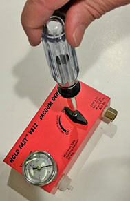
Step 1: Remove end caps with screw driver or thin tool.
Step 2: Remove Air-In brass fitting
Step 3: Check screen inside Air-In brass fitting for debris – clean if needed.
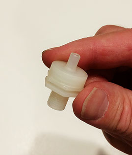
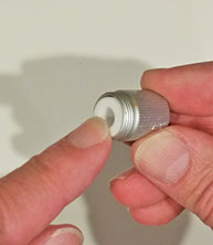
Step 4: Remove vacuum filter (white fitting).
Caution: Use wrench carefully on flats or more damage could result.
Step 5: Check screen inside filter for debris – clean or replace if needed.
Caution: Screen inside filter is very fine and delicate.
Step 6: Remove valve handle
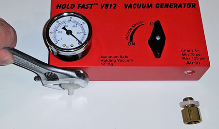
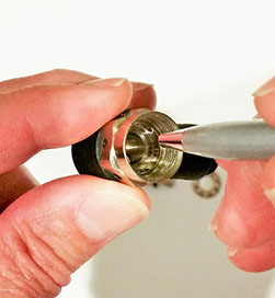
Step 7: Remove Vacuum Gauge by twisting with your hand. Use a 7/16” end wrench if needed.
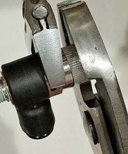
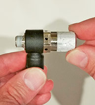
Step 8: Pull assembly out of the case. Note position of valve lever limiter (aluminum part on valve – will fall off).
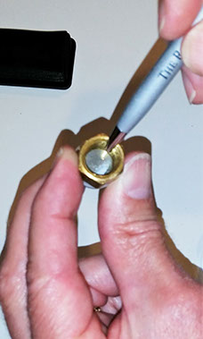
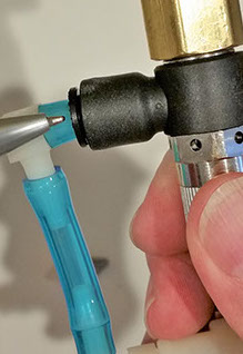
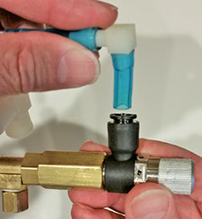
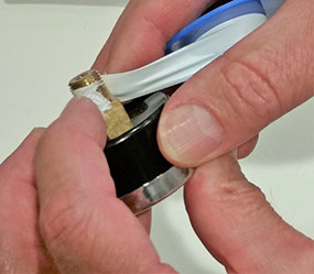
Step 9: Remove blue hose from black fitting. This fitting is a press-in fitting and the collar needs to be depressed.
Note: Image shows the pen pointing to the collar that needs to be depressed to release the hose.
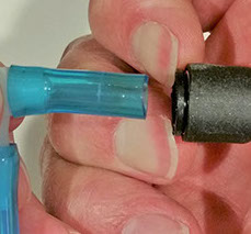
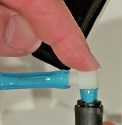
Step 10: Depress both sides of the collar while pulling hose out of fitting.
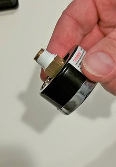
Step 11: Remove hose. Collar shown is still depressed
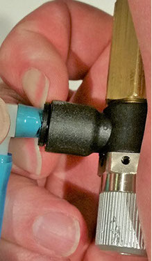
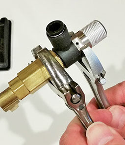
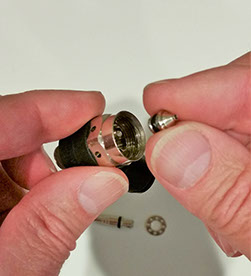
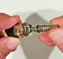
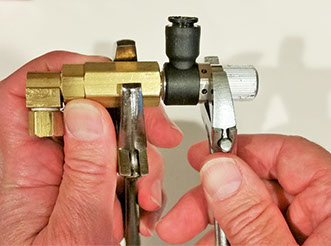
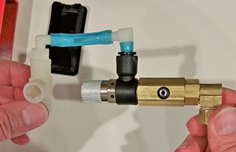
Step 12: Disassemble On/Off Valve from vacuum venturi. Use wrenches on flats.
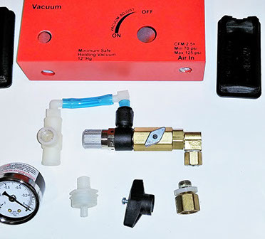
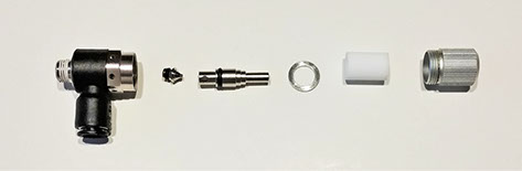
Step 13: Shown completely disassembled
How to Disassemble and Clean Vacuum Venturi
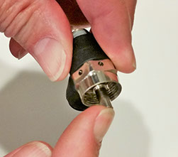
Step 1: Remove Knurled Cap from body, using wrench on flats and pliers if needed. Unthreading by hand may be all that is required. Note: There is a retaining washer that may or may not have vent holes and a white muffler may fall out.
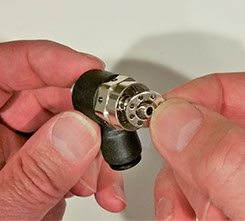
Step 2: Remove White Muffler from Knurled Cap. Push out with paper clip if required. Clean if necessary.
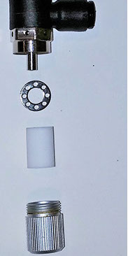
Venturi with muffler and retaining washer removed
Step 3: Remove center post. Pull straight out by hand.
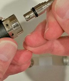
Step 4: Push out insert from threaded side with a paper clip.
Note: Be ready for a very small part to pop out of the other end.
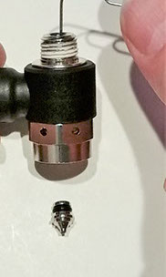
Step 5: Venturi is now completely disassembled and ready for cleaning.
(shown with solid style retaining washer)
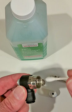
Step 6: Clean with isopropyl alcohol, swabs, rags, and compressed air
How to Reassemble Vacuum Venturi
Step 1: Insert small part. Add a light silicone grease on O-ring if needed.
Step 2: A slim line pen with pen retracted will help center and seat small part into hole.
Step 3: Insert post into body. Add a light amount of silicone grease on O-ring if needed.
Step 4: Press to fully seat
Step 5: Install retaining ring over post (either as shown or solid ring)
Step 6: Install white muffler into knurled knob – open hole facing out
Step 7: Screw knurled knob onto body. Tighten by hand. You may need a wrench on the flats to hold body from turning while tightening knurled knob.
Note: black portion is designed to rotate allowing easy positioning when installing into case.
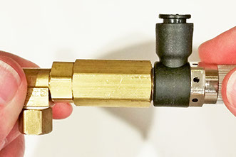
Step 8: Reattach Vacuum Venturi to On/Off Valve Body (If Teflon tape is used – keep tape below the first few threads to keep the tape from shredding and clogging the Venturi).
Step 9: Tighten and align the black hose fitting opposite from the fitting on the other side of the valve. This can be done by rotating the black portion of the Venturi, which will rotate around.
Step 10: Insert blue hose into Venturi fitting
Step 11: Press hose to completely seat into press lock fitting
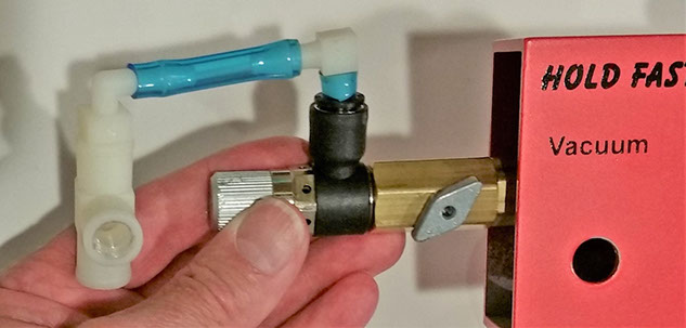
Step 12: Assembled. Check to make sure other hose connections are secure.
Step 13: Reinstall Aluminum valve limiter into place and slip assembly into case.
Step 14: Reinstall Air-In Fitting and ONLY hand tighten at this point.
Step 15: Reinstall Vacuum Filter and ONLY hand tighten.
Step 16: Apply Teflon tape or liquid thread sealer to Vacuum Gauge threads
Step 17: Leave the first few threads clear to keep tape from shredding and clogging venturi.
Step 18: Reinstall Vacuum Gauge – HAND TIGHTEN ONLY. Stop when aligned to read before bottoming out. If Gauge does not align to read and has bottomed out – LOOSEN the gauge.
DO NOT OVER TIGHTEN. The Teflon tape will keep from leaking and does not need to be tight.
If desired, a spacer/washer can be added over the Gauge threads to allow the gauge to bottom out at a higher height and be tight. Hand Tighten Only.
Step 19: Reinstall Valve Knob
Step 20: Reinstall end caps – press into case.
Step 21: Tighten Air-In fitting with wrench.
Step 22: Tighten Vacuum Filter – ONLY SNUG. DO NOT OVER TIGHTEN.
Step 23: That is it! FINISHED – with the tools you used
Test Assembly
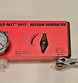
Connect clean compressed air at 85psi or more to Air-In
Put finger over white Vacuum Filter opening
Rotate Valve to full ON
Check Vacuum typical at Sea Level 20"-25"+hg
NOTE: Air escaping from the case is normal from inside the case. The internal Venturi uses compressed air to create vacuum.